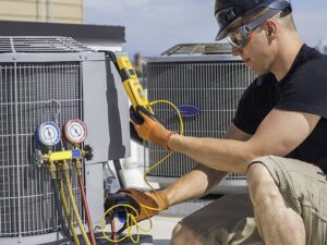
In recent blogs, we have covered why and how you need to install security camera systems. Now it is time we discuss what to do about the tangle of wires during an installation, which makes you wonder which wire connects where. Splicing security camera wires is a task that can feel intimidating at first, but once you understand the 4-wire color diagram, it’s actually pretty doable. Whether you’re installing your first camera or adding to an existing system, this home security camera wired install guide will walk you through it all with clear, real-life tips.
Why Wire Colors Matter in Security Camera Setup
Color coding is the universal language of wiring. In the world of security cameras, it’s not just about keeping things tidy—it’s crucial for functionality. Misconnecting wires doesn’t just confuse; it can lead to short circuits, loss of video feed, or even damage your equipment.
When you understand the security camera wire color diagram, you’re ensuring each signal travels correctly from the camera to the DVR or NVR. It helps you prevent costly mistakes and makes troubleshooting way easier later.
- Prevents signal crossover or power issues
- Simplifies the installation process
- Aids in future maintenance or upgrades
- Ensures consistent system performance
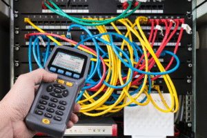
Understanding CCTV Camera Cables and Connectors
When it comes to wiring your CCTV system, knowing your cable and connector types makes all the difference. For analog systems, coaxial cables—especially RG59 siamese cables—are commonly used. They transmit unprocessed video signals and come paired with power wires in one casing. On the other hand, Ethernet cables are the go-to for IP cameras, offering fast video transmission and the ability to power devices through Power over Ethernet (PoE).
Connectors also play a critical role. Wires without connectors are almost useless. They can’t do the job alone—connectors are the unsung heroes that bring your CCTV system to life. BNC connectors are typical for coaxial setups, known for their twist-lock mechanism. RJ45 connectors are used for Ethernet and IP systems, while RCA connectors are often seen in plug-and-play options for quick audio and video hookups.
Choosing the Right Cable: Shielding, Convenience, and Performance
Not all cables are created equal. Shielded cables—like coaxial siamese and shielded Ethernet—help prevent interference, which is especially important in high-interference areas. Unshielded cables, often found in plug-and-play options, are easier to install but more prone to signal loss and noise. Ethernet cables, in particular, are affordable, flexible, and widely available—ideal for new installations or upgrades.
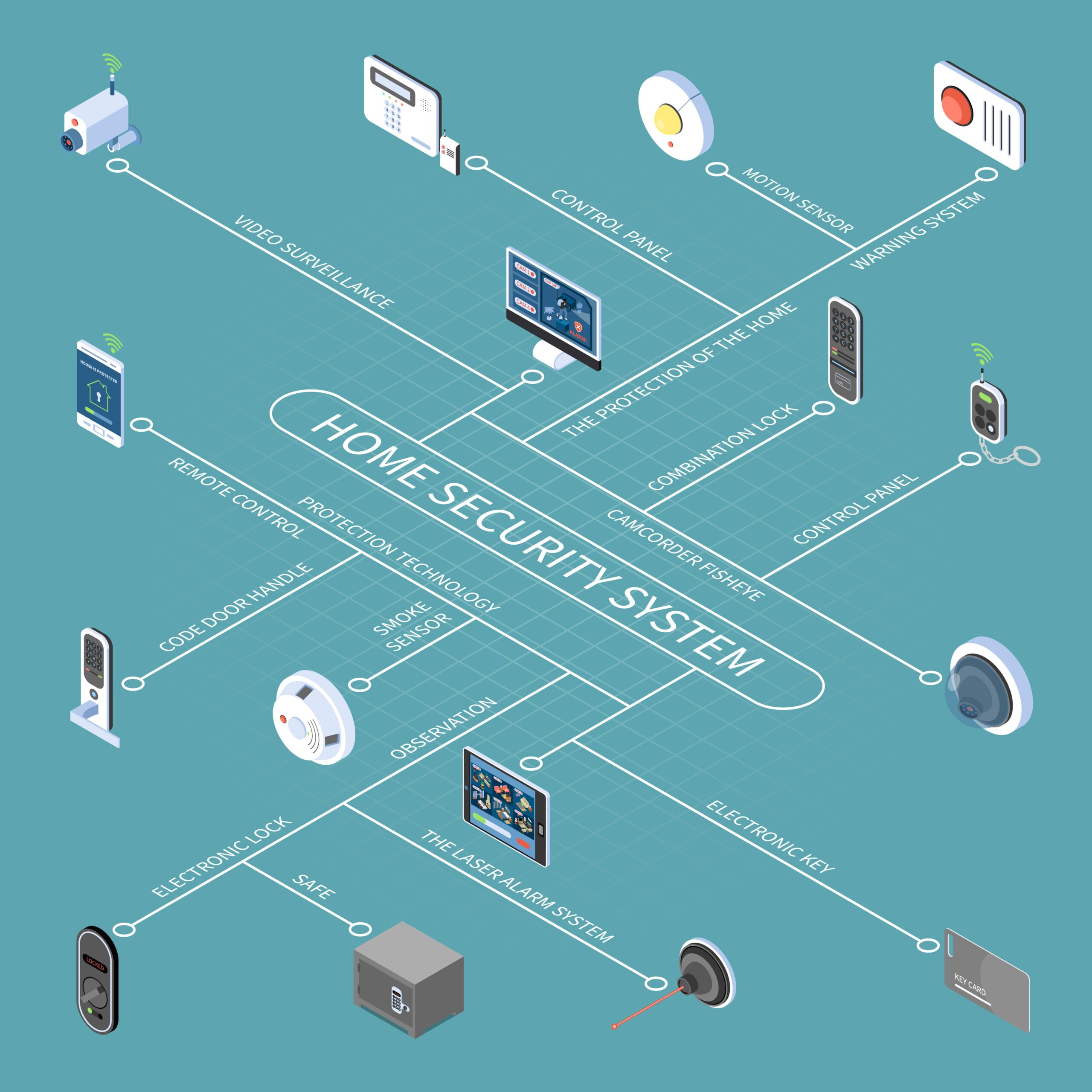
What is a 4-Wire Security Camera Wiring Diagram?
The 4 wire diagram is one of the most common formats for analog security camera systems. It splits key functionalities—video, power, ground, and audio/data—into four distinct wires. These wires are color-coded to avoid confusion and make splicing straightforward.
Knowing these colors allows you to identify the role of each wire during installation and splicing, even without a manual. This is especially useful when extending wires or replacing damaged sections.
- Red – Power (12V or 24V DC)
- Black – Ground (negative terminal)
- Yellow – Video signal (typically BNC connection)
- White or Blue – Audio or Data/Control line
Understanding the Splicing Process
Splicing wires means cutting and joining wire segments together securely. It is fixing or extending your wires the right way, and doing it clean and safe. This is often needed when wires are too short or damaged. It’s crucial to use proper techniques to avoid signal loss, corrosion, or electrical hazards.
Always work with powered-off systems and use weather-resistant materials if the camera is outdoors. A clean, tight splice means better performance and longer wire life.
- Strip 1/2 inch of insulation from each wire
- Match wire colors exactly
- Twist wires tightly and seal with tape or wire nuts
- Use waterproof connectors outdoors
How to Run Security Camera Wires Through Walls
Running wires through walls gives your system a professional and tidy appearance. It takes some effort, but the results are worth it. Planning your path in advance and using proper tools prevents damage to walls and wiring.
Use attic spaces, crawl spaces, or baseboards to hide wires. Keep a clear route from the camera to the DVR or power source.
- Use a fish tape or wire puller
- Drill near the camera mounting area
- Label each end of the wire
- Use wall bushings or grommets
How to Run Security Camera Wires Outside
Installing cameras outside introduces extra challenges—weather, UV rays, and potential tampering. Protecting your wiring ensures reliability and longer lifespan.
Think of conduits, cable clips, and quality insulation as your go-to protection tools. They protect your wires from weather damage, physical wear, and accidental disconnections. Always try to keep wires high up and securely fastened to prevent tripping hazards or exposure to moisture.
- Use UV-resistant, weatherproof cables
- Run wiring through PVC or metal conduit
- Avoid sagging or low-hanging wires
- Seal all entry points to prevent moisture
Wiring Outdoor Security Cameras: Mistakes to Avoid
Installing outdoor cameras? Great—but beware of common wiring errors. Using the wrong materials or skipping vital steps can make your entire setup vulnerable.
It’s better to do prior research and spend time on proper installation than deal with expensive repairs or system failures later.
- Never use indoor-rated wire outdoors
- Don’t leave splices exposed to the elements
- Always ground your system
- Follow diagrams exactly when splicing
How to Install Security Camera Wiring Correctly
Correct installation is about more than just connecting wires—it’s about reliability and safety. A well-installed system delivers clear footage and needs fewer repairs down the line.
By labeling, testing, and protecting your wires, you lay the foundation for a system that runs smoothly for years.
- Identify your camera type (IP or analog)
- Use a trusted 4-wire color diagram
- Always secure wires with clamps or ties
- Test the video and power before sealing everything
The Role of BNC in 4-Wire Color Diagrams
In analog CCTV setups, BNC connectors are often used for the video signal. These twist-lock connectors ensure a tight and reliable signal path, which is crucial for high-quality video feeds.
Splicing with BNC requires precision, but once done right, it significantly reduces noise and signal degradation.
- The yellow wire connects to the BNC for video
- Power wires use barrel connectors or terminal blocks
- Match the wire gauge when splicing to BNC cables
- Use crimp tools or BNC compression connectors
Advanced Setups: 5 Wire and 8 Wire Diagrams
As technology advances, so do the wiring demands of modern security systems. These systems sometimes go beyond the basic 4-wire model. PTZ (pan-tilt-zoom) cameras and smart home setups often require more control lines and power needs.
Knowing the basics of these configurations can help if you decide to upgrade or work with more complex devices in the future.
- 5 Wire includes extra control for PTZ functions
- 8 Wire usually supports Ethernet or PoE systems
- Useful for advanced camera functionality
- Often comes pre-labeled for easier setup
Conclusion:
No matter where you’re installing your cameras—indoors, outdoors, or in a commercial setup—understanding the color code splicing security camera wires makes everything smoother and easier. And tidy wires and well-installed systems are a relief for the days to come. Take your time, follow the diagrams, and stay safe while handling wires. Once you’ve nailed the surveillance camera wiring diagram, you’ll feel much more confident tackling any home security camera wired install project in the future.